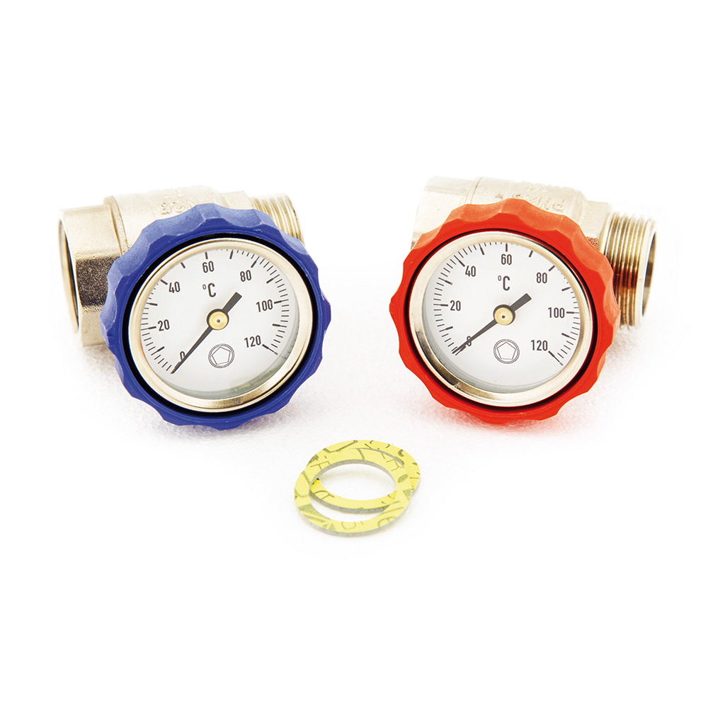
1″ Isolation Ball Valves with Temperature Gauges – Red & Blue Pair
$ 92.12
Out stock
Flow and return temperature monitoring Each valve incorporates a temperature gauge, allowing the temperatures at both manifold connections to be viewed locally. The red and blue identification helps distinguish the two sides of the installation during commissioning and maintenance. The gauges provide temperature indication only. They do not regulate the water temperature or replace the mixing, heat-source or safety controls required by the UFH system design. Manifold isolation for maintenance and testing The ball valves allow the manifold to be isolated from the primary heating circuit. Ambiente’s commissioning guidance instructs installers to close the manifold isolation valves when filling, flushing or pressure testing the individual UFH circuits. Providing isolation immediately beside the manifold also allows suitable components to be inspected or serviced without unnecessarily draining the complete primary heating system, subject to the installation arrangement. Compatible 1″ manifold connections The valves have 1″ female-to-male threaded connections and are listed as an accessory for Ambiente manifolds with product codes beginning 413. The 413 Series Stainless Steel Manifold has compatible 1″ primary connections. Compatibility with manifolds from other ranges or manufacturers should be checked before ordering, including the thread type, sealing arrangement, available installation space and direction of flow. Installation and sealing The valves should be installed in an accessible position so the controls and temperature gauges remain visible. Appropriate sealing components must be used for the specific threaded connection, including the correct 1″ fibre washer where required. The valves and connections should be checked for leaks before the system is commissioned. Installation must follow the manifold and complete heating-system instructions.
Related Products
-6%
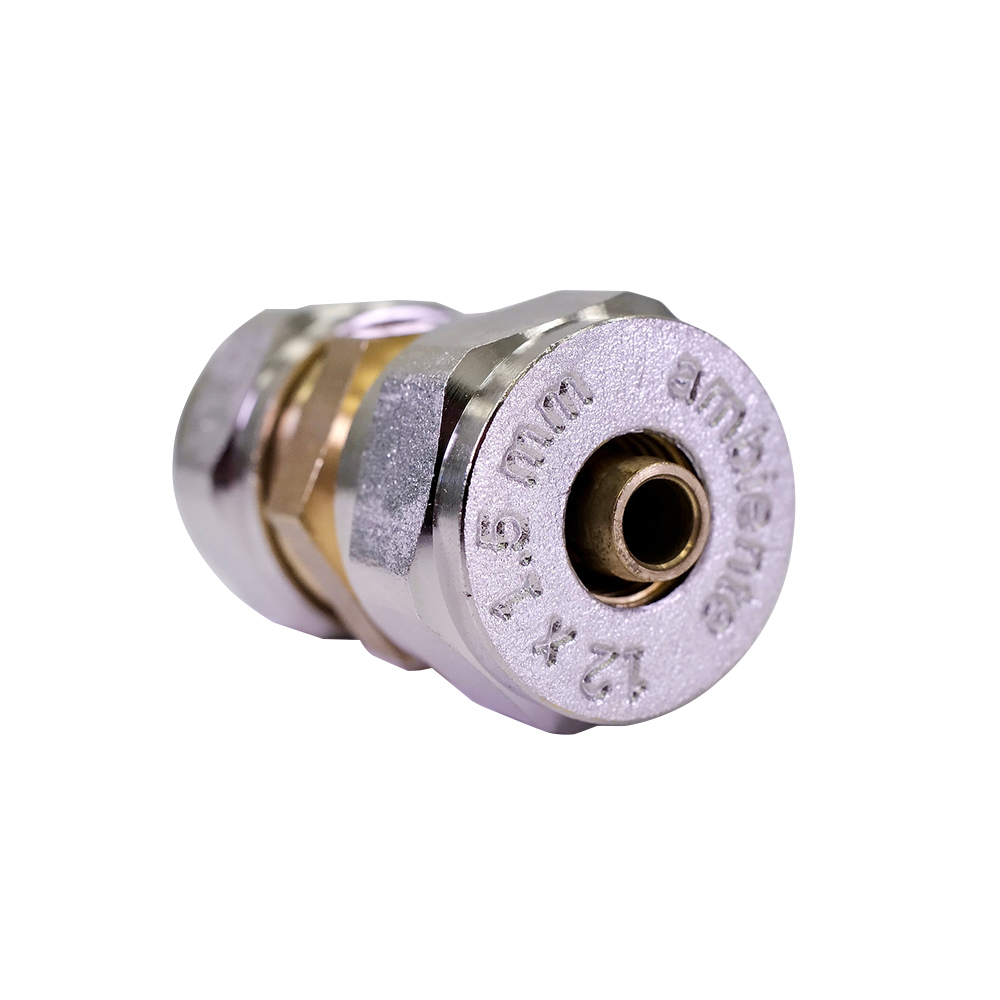
3/4″ Repair for 12mm Pipe
$ 11.94-7%

Out Of Stock